![]()
HomeGenie mini (code name Sbirulino) is an open source library for building custom firmware for smart devices based on ESP32 or ESP8266 chip.
- Easy device configuration using Wi-Fi protected setup button (WPS) or Bluetooth
- Does not require an Internet connection to be configured or to work properly
- Time synchronization using internal RTC (ESP32), mobile app time or NTP
- Integrated actions scheduler supporting extended cron expressions
- Device discovery via SNMP/UPnP with customizable advertising name
- Multi-channel I/O: HTTP, WebSocket, SSE, MQTT, Serial
- Status LED
- Configuration/Pairing Button
- Builtin GPIO control API
- Multi-threading support, event router, extensible API
- Can connect directly to HomeGenie Panel either via Wi-Fi access point or hotspot/tethering
- Can be easily connected to HomeGenie Server and other services via MQTT
The firmware can be installed using Platform.IO core CLI.
After installing Platform.IO core, download HomeGenie Mini source code,
unzip it and open a terminal with the current directory set to homegenie-mini folder.
Then enter the following commands to install libraries required to build the firmware:
pio update
pio lib install
To actually build and install HomeGenie Mini firmware, connect your ESP device to your PC's USB port and issue the command:
pio run -e default -t uploadCongratulations!! =) You've just got a new shiny HomeGenie Mini device up and running.
The option -e default shown in the previous command is used to specify the configuration environment.
The default environment is for building the base firmware for a generic ESP32 board.
To list all available configurations enter the following command:
pio project configBy editing the platformio.ini file is possible to add custom configurations to build your own version
of the firmware to support different hardware and functionality.
Once the firmware is installed you can configure and control the device using the HomeGenie Panel app available on Google Play.
The status LED of the device will blink continuously indicating that it is not
connected to Wi-Fi.
The device can be configured and connected to Wi-Fi very easily by enabling
WPS on your router and by pressing the WPS button on the device for at least 5
seconds. The status LED will stop blinking and stay on while the WPS mode is
active on the device.
After pairing, the device will start blinking quickly again for about 5 seconds, and then it will blink slowly indicating that is connected correctly to Wi-Fi. It will then appear in the list of detected devices in the connections discovery page of HomeGenie Panel.

Select it from the list and click the "Done" button.
If WPS is not available on your router, you can alternatively set up your device via Bluetooth if it is enabled on your phone when you start the connection discovery process on the HomeGenie Panel.
The new HG-Mini device will be detected via Bluetooth and the app will display a dialog to configure the device name and data to connect it to Wi-Fi. After confirming the settings, the HG-Mini device will exit pairing mode, reset and connect to Wi-Fi.
Depending on the installed firmware version you will be able to select different kind of modules
to show in the panel dashboard. The following picture refers to the smart-sensor-d1-mini-esp32
firmware that implements temperature and light sensor and 4 GPIO switches.

HG-Mini devices can also be connected to HomeGenie Server configuring the MQTT client as shown in the following picture.

Is then possible to use HG-mini device for automation tasks, logging, statistics and use of all other features available in HomeGenie Server.

When the device is connected to your PC's USB port, you can monitor its activity logs by entering the following command::
pio device monitor -b 115200Example output
[1970-01-01T00:00:00.055Z] HomeGenie Mini 1.2.0
[1970-01-01T00:00:00.056Z] Booting...
[1970-01-01T00:00:00.057Z] + Starting HomeGenie service
[1970-01-01T00:00:00.068Z] + Starting NetManager
[1970-01-01T00:00:00.068Z] |  - Connecting to WI-FI .
[1970-01-01T00:00:00.187Z] |  - WI-FI SSID: HG-NET
[1970-01-01T00:00:00.188Z] |  - WI-FI Password: *
[1970-01-01T00:00:00.214Z] |  x WiFi disconnected
[1970-01-01T00:00:00.774Z] |  ✔ HTTP service
[1970-01-01T00:00:00.784Z] |  ✔ WebSocket server
[1970-01-01T00:00:00.786Z] |  ✔ MQTT service
[1970-01-01T00:00:00.791Z] @IO::GPIO::GPIOPort [Status.Level 0]
[1970-01-01T00:00:00.792Z] :Service::HomeGenie [IOManager::IOEvent] >> [domain 'HomeAutomation.HomeGenie' address '14' event 'Status.Level']
[1970-01-01T00:00:00.807Z] @IO::GPIO::GPIOPort [Status.Level 0]
[1970-01-01T00:00:00.809Z] :Service::HomeGenie [IOManager::IOEvent] >> [domain 'HomeAutomation.HomeGenie' address '27' event 'Status.Level']
[1970-01-01T00:00:00.822Z] READY.
[1970-01-01T00:00:00.823Z] @IO::Sys::Diagnostics [System.BytesFree 147128]
[1970-01-01T00:00:00.835Z] :Service::HomeGenie [IOManager::IOEvent] >> [domain 'HomeAutomation.HomeGenie' address 'mini' event 'System.BytesFree']
[1970-01-01T00:00:00.848Z] :Service::EventRouter dequeued event >> [domain 'HomeAutomation.HomeGenie' address 'mini' event 'System.BytesFree']
[2023-12-29T17:01:11.050Z] |  - RTC updated via TimeClient (NTP)
[2023-12-29T17:01:11.053Z] |  ✔ UPnP friendly name: Bagno
[2023-12-29T17:01:11.054Z] |  ✔ SSDP service
[2023-12-29T17:01:11.200Z] |  - Connected to 'HG-NET'
[2023-12-29T17:01:11.201Z] |  - IP: 192.168.x.y
[2023-12-29T17:01:15.048Z] @IO::Sys::Diagnostics [System.BytesFree 143268]
[2023-12-29T17:01:15.049Z] :Service::HomeGenie [IOManager::IOEvent] >> [domain 'HomeAutomation.HomeGenie' address 'mini' event 'System.BytesFree']
[2023-12-29T17:01:15.063Z] :Service::EventRouter dequeued event >> [domain 'HomeAutomation.HomeGenie' address 'mini' event 'System.BytesFree']
HomeGenie Mini device support also commands via serial terminal. You can enter any API
command using the /api/ prefix, or enter system commands prefixed by # character.
#CONFIG:device-name <name>
#CONFIG:wifi-ssid <ssid>
#CONFIG:wifi-password <passwd>
#CONFIG:system-time <hh>:<mm>:<ss>.<ms>
#CONFIG:system-zone-id <zone_id>
#CONFIG:system-zone-offset <tz_offset>
#VERSION
#RESET
#GET:<key>
#SET:<key> <value>
| Key | Description | Default |
|---|---|---|
sys-rb-n |
Factory reset button GPIO# | -1 (-1=not used) |
sys-sl-n |
System status LED GPIO# | -1 (-1=not used) |
io-typ01 |
I/O Ch.1 type | |
io-pin01 |
I/O Ch.1 GPIO# | -1 (-1=not used) |
io-typ02 |
I/O Ch.2 type | |
io-pin02 |
I/O Ch.2 GPIO# | -1 (-1=not used) |
io-typ03 |
I/O Ch.3 type | |
io-pin03 |
I/O Ch.3 GPIO# | -1 (-1=not used) |
io-typ04 |
I/O Ch.4 type | |
io-pin04 |
I/O Ch.4 GPIO# | -1 (-1=not used) |
io-typ05 |
I/O Ch.5 type | |
io-pin05 |
I/O Ch.5 GPIO# | -1 (-1=not used) |
io-typ06 |
I/O Ch.6 type | |
io-pin06 |
I/O Ch.6 GPIO# | -1 (-1=not used) |
io-typ07 |
I/O Ch.7 type | |
io-pin07 |
I/O Ch.7 GPIO# | -1 (-1=not used) |
io-typ08 |
I/O Ch.8 type | |
io-pin08 |
I/O Ch.8 GPIO# | -1 (-1=not used) |
Example setting configuration from a terminal connected to the serial port of the device:
#SET:sys-sl-n=10
#SET:sys-rb-n=0
#RESET
Example getting configuration value:
#GET:sys-sl-n
response:
#GET:sys-sl-n=10
In the examples folder you can find some smart device projects using HomeGenie Mini library.
You can use the following command to list all possible configurations to build the examples:
pio project configSee also HomeGenie Mini Documentation for further information about included examples.
THIS PROJECT IS PROVIDED BY THE COPYRIGHT HOLDERS AND CONTRIBUTORS "AS IS" AND ANY EXPRESS OR IMPLIED WARRANTIES, INCLUDING, BUT NOT LIMITED TO, THE IMPLIED WARRANTIES OF MERCHANTABILITY AND FITNESS FOR A PARTICULAR PURPOSE ARE DISCLAIMED. IN NO EVENT SHALL THE COPYRIGHT OWNER OR CONTRIBUTORS BE LIABLE FOR ANY DIRECT, INDIRECT, INCIDENTAL, SPECIAL, EXEMPLARY, OR CONSEQUENTIAL DAMAGES (INCLUDING, BUT NOT LIMITED TO, PROCUREMENT OF SUBSTITUTE GOODS OR SERVICES; LOSS OF USE, DATA, OR PROFITS; OR BUSINESS INTERRUPTION) HOWEVER CAUSED AND ON ANY THEORY OF LIABILITY, WHETHER IN CONTRACT, STRICT LIABILITY, OR TORT (INCLUDING NEGLIGENCE OR OTHERWISE) ARISING IN ANY WAY OUT OF THE USE OF THIS PROJECT, EVEN IF ADVISED OF THE POSSIBILITY OF SUCH DAMAGE.
(click the picture above to watch the video)
Hardware features
- WPS button for quick Wi-Fi protected setup
- Temperature and light sensors
- RF transceiver (315/330/433Mhz)
- Expansion connector (P1) with 4 GPIO configurable as SPI/DIO/PWM
Example applications of the P1 connector:
- control up to 4 relays to actuate lights and appliances (DIO)
- hosting additional sensors, connecting a display or other hardware (SPI)
- control the brightness of a LED or drive a motor at different speed (PWM)
- breadboard playground
Firmware features
- Automatic discovery (SSDP) for instant client setup
- GPIO mapping to virtual modules: switch for digital output, dimmer for analog output or sensor for inputs (work in progress)
- X10 home automation RF protocol encoding and decoding with mapping to virtual modules
- Modules state persistence
- HTTP API (subset of standard HomeGenie API)
- Real time event stream over WebSocket or SSE connection
- MQTT broker over websocket
- NTP client for time sync
- Scripting engine (work in progress)
- Serial CLI with same API as HTTP
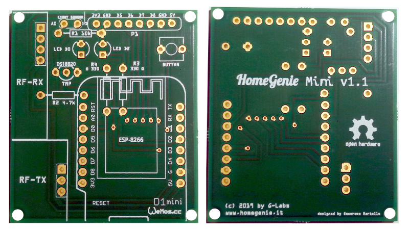
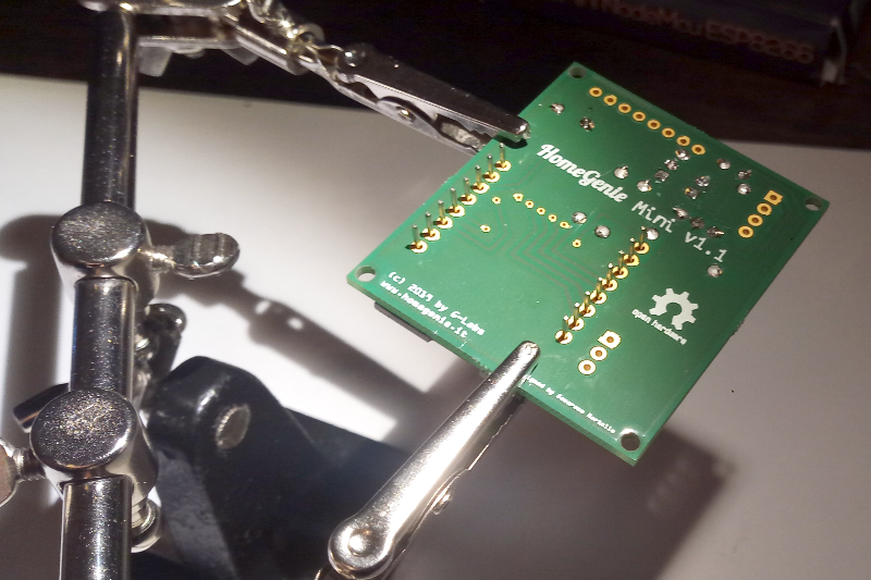
HomeGenie Mini board front and rear view
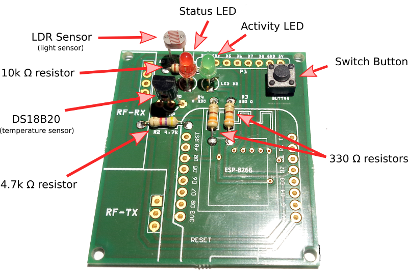
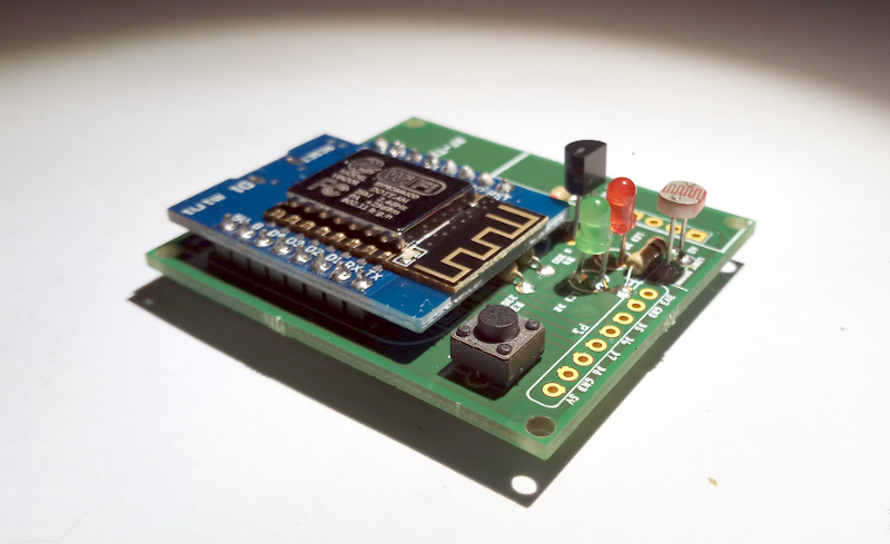
STEP 1: Start by soldering the 3 resistors, 2 LEDs, light sensor, temperature sensor and the momentary switch button
STEP 4: Optionally solder the RF receiver and transmitter: the firmware currently only support X10 home automation protocol. More protocols might be added in the future (any request?).
The picture below shows a basic HomeGenie Mini device without the RF transceiver but adding the RF transceiver is easy as solder two more components. You can also take advantage of the expansion port (P1) to connect a relay module to control lights and appliances or any other additional sensors/components required for your projects.
Gerber files required for printing the circuit board are located in the ./pcb folder.
You can use the Gerber file and autonomously get HomeGenie Mini board manufactured from any PCB print service.
If just need a few boards you can get 3 boards for less than $20 from AISLER. Open AISLER website and click Get Started then you will be able to upload HomeGenie Mini Gerber file and order your PCBs.
The PCB size is 44mm*50mm.
Components listing
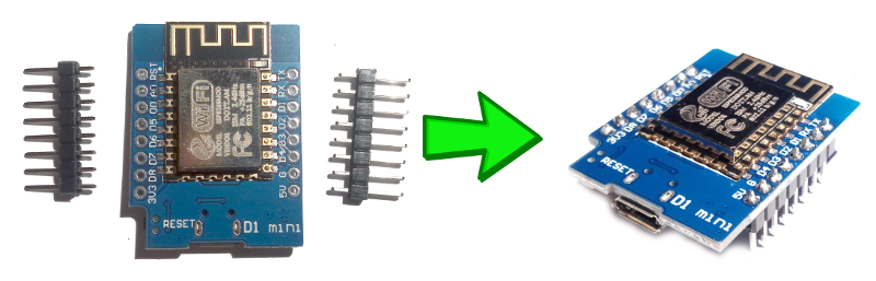
- 1 ESP8266 WeMoo D1 mini Wi-Fi module (or equivalent)
- 1 DS18B20 (temperature sensor)
- 1 LDR (light sensor)
- 1 FS1000A (RF transmitter)
- 1 XY-MK-5V (RF receiver)
- 1 R1 10kΩ
- 1 R2 4.7kΩ
- 1 R3 330Ω
- 1 R4 330Ω
- 2 LED 3mm
- 1 Push button 6mm*6mm
Source code
Release