WiFi thermostat based on the ESP32 (Espressif WROOM-32 Developer Kit), using several SHT3X(SHT31-D) temperature/humidity sensor and ILI 9341 TFT LCD Touch display. Data are sent to the Blynk server. Thermostat can be controlled by the Blynk application from iPhone or directly by touch on the LCD. Project is free to use, coded in C++, created in Visual Code with PlatfomIO IDE.
To build a project, you need to download all the necessary libraries and create the settings.cpp file in the src folder with specific settings:
// address 1 - enable/disable heating
#define EEPROM_ENABLED_DISABLED_HEATING_ADDRESS 1
// address 2 - target temperature
#define EEPROM_TARGET_HEATING_TEMPERATURE_ADDRESS 2
// address 3 - target temperature was set from display
#define EEPROM_TARGET_HEATING_TEMPERATURE_DISPLAY_SET_ADDRESS 3
// address 4 - heating enabled/disabled was set from display
#define EEPROM_ENABLED_DISABLED_HEATING_DISPLAY_SET_ADDRESS 4

#define MAX_TEMPERATURE_FROM_DISPLAY 25
#define MIN_TEMPERATURE_FROM_DISPLAY 10

// Thermostat project settings
struct Settings
{
    const char *ssid = "WIFI ssid";
    const char *password = "WIFI password";
    const char *blynkAuth = "blynkAuthDevice1";
    const char *blynkAuthOutdoor = "blynkAuthDevice2";
    const char *blynkAuthBedroom = "blynkAuthDevice3";
    const char *blynkAuthPantry = "blynkAuthDevice4";
    const char *hostNameOTA = "OTA host name";
    const char *passwordOTA = "OTA password";
    const char *version = "0.1.0";
};I'm using awasome TFT_eSPI library from Bodmer. You must update User_Setup.h file to set display type and pins. There is ESP32 section, my setup for this section is following:
// ###### EDIT THE PIN NUMBERS IN THE LINES FOLLOWING TO SUIT YOUR ESP32 SETUP   ######

// For ESP32 Dev board (only tested with ILI9341 display)
// The hardware SPI can be mapped to any pins
#define TFT_MISO 19
#define TFT_MOSI 23
#define TFT_SCLK 18
#define TFT_CS   15  // Chip select control pin
#define TFT_DC    2  // Data Command control pin
#define TFT_RST  -1  // Set TFT_RST to -1 if display RESET is connected to ESP32 board RST
#define TOUCH_CS  4  // Chip select pin (T_CS) of touch screen
For wires connection between the display and the ESP32 look to the schema..
When you have 5V relay, there is a need to think about 3.3V ESP32 pins. You can't just connect ESP32 pin to source pin of the relay, it would not work. One way is insert MOSFET between ESP32 pin and source pin of the relay. Other solution is just use the 3.3V relay, or solid state relay. More information is here.
- ESP32 Espressif WROOM-32 Developer Kit
- HLK-PM01 220v to 5v power supply
- Relay module shield
- 2.8" SPI TFT LCD Touch Panel
- SHT3X (SHT-31D) temperature and humidity sensor
- Button, Mosfet

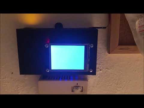
How the finished project works is shown in this YouTube video.