In this project, the Eddie robot from Parallax has been modified to implement its autonomous navigation ability as well as other functionalities of a robotic system base on the Robot Operating System (ROS).
ROS navigation stack is used to provide the autonomous navigation functionality for our robot. The requirements to run the navigation stack properly based on our hardware specifications are fulfilled by implementing our own custom ROS packages as well as using existing packages provided by the ROS community.
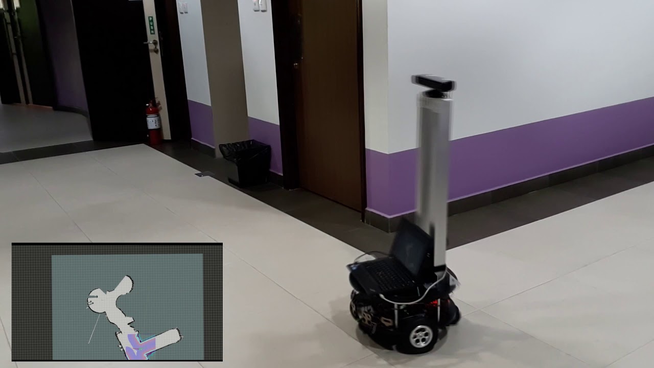
If you have found this repository useful or have used this repository in any of your scientific work, please consider citing my work using this BibTeX Citation. A full demonstration video of the mobile robot navigation has been uploaded on Youtube.
- Hardware setup
- Software structure
- Getting started
- Libraries used in writing programs
- Imported ROS packages in the system
- Satisfying ROS package dependencies
- Setting up the individual computers to run the system
- Running the Robot operation
- Visualization of ROS topics
- BibTeX Citation
- Acknowledgments
There are three computers involved in our setup, two local computers which are equipped on the robot platform and a single remote computer. Wired LAN is used for communication between the two local computers while WLAN is used for communication between the local and remote computers as shown below.

Local computer
A Raspberry Pi 3 model B is equipped on Eddie to interface with the sensors and motors to run odometry computations and move Eddie respectively.
Due to the low computational power of Raspberry Pi, a separate laptop computer is used to run the more computationally demanding functionalities such as SLAM, navigation, face detection and high level behaviors.
Note that the Kinect may be connected to either the Pi OR the laptop (preferred).
Remote computer
Any remote computer can be used as user interface to send commands to Eddie's onboard computer and also to run visualization software provided by ROS.
The remote computer eases the visualization, remote monitoring and control. The robot can operate autonomously without the remote computer.
Circuit diagrram
The diagram below shows the connections from the Raspberry Pi to the sensors and actuators. Step down power modules are used to provide the 5V and 12V power supply to the circuit.

The components used include:
- 1 x Raspberry Pi 3 Model B
- 2 x Parallax Aluminum Motor Mount & Wheel Kit with 36-position disk Quadrature Encoders that resolve to 144 encoder positions per revolution
- 2 x Parallax HB-25 Motor Controller
- 2 x Pololu adjustable 4-12V Step-Up/Step-Down Voltage Regulator S18V20ALV
The circuit is powered by three 14.4V LiPo battery.
The diagram below shows the software structure based on the ROS.

Firstly, we need to install ROS in all the three computers. ROS community has already provide a detailed installation guide. It is highly recommended to use Ubuntu as it is the main development platform for ROS.
There are two main folders in the repository named Pi and Laptop which contains custom ROS packages.
As the name suggests, the folder contents should go to their respective ~/catkin_ws/src/custom_packages
of the computers.
Please note that in the current system, the
custom_packagesfolder are simply for convenience to store your own custom implementations while theimported_packagesfolder is to store packages cloned from ROS community. You may omit these folder naming conventions if you wish.
Python2.7 is the programming language used for all implementations. The list of libraries used can be installed using
pip install command.
Pi computer and Laptop computer
- Robot Operating System - The robot framework and development environment
Pi computer
- RPi GPIO - The library used for controlling GPIO ports of Raspberry Pi
- pigpio - The library used for PWM of motors
Laptop computer
- OpenCV - The library used in face detection implementation
- PlaySound - The library used in behavior implementation
In addition to our own packages, external packages from ROS are also used. Simply clone the respective packages
into ~/catkin_ws/src/imported_packages and compile.
Pi computer
Laptop computer
You may notice that after cloning all the packages, running catkin_make produced errors and failed to compile the
workspace. In addition, even if it has successfully compiled -- running the node may yield some error resulting
in the package not running at all when executed. This is due to missing dependencies required by the package.
Installing these dependencies is the same as cloning packages from a repository and compiling the workspace.
Pi computer
robot_odometry
openni_camera
depthimage_to_laserscan
Laptop computer
robot_transforms
openni_camera
depthimage_to_laserscan
navigation
- None, the package itself contains required dependencies
gmapping
explore_lite
At this point, running catkin_make and running individual packages should be successful.
for
gmapping, please refer to "Quigley's programming with ROS Robots" book on the parameter tuning. The default tuning is not suitable for use with Kinect sensor.
Before running the packages, we need to check if the computers are able to communicate with each other with the current hardware setup. Thankfully, ROS community has provided a useful wiki on how to test this.
Step 1: Network setup between local computers (Raspberry Pi and Laptop)
The WLAN from the robot's local computer will be shared to Raspberry Pi through an ethernet cable as
shown in the diagram earlier in Hardware Setup. Run the following on your terminal and follow the guide.
nm-connection-editor
If everything runs smoothly, you should be able to ping between the two local computers. At this point, the entire robot system is ready to be run. However, the remote computer would not be able to subscribe to topics published from the Rapsberry Pi. We will address this issue in step 2.
Step 2: Network setup between robot computers (Raspberry Pi and Laptop) and remote computer
The master needs to be able to communicate and reach to all computers involved in order to successfully send and receive topics. So we are going to use the laptop computer as a WIFI hotspot for the remote computer to connect to. Since it is not possible to both connect to the existing WIFI and broadcast a WIFI hotspot using the laptop internal WIFI module, we will be using an external WIFI USB adapter to connect to the existing WIFI and use the internal WIFI module to broadcast a WIFI hotspot for the remote computer to connect to.
Sharing wireless internet connection through wireless hotspot
Once completely setup, connect to the newly created hotspot with a remote computer.
Step 3: Setting up the ROS network
Example of ~/.bashrc file with our current setup:
Robot computer 1 (Raspberry Pi)
eth0 IP: 10.42.0.179
[...]
export ROS_IP=10.42.0.179
export ROS_MASTER_URI=http://192.168.31.123:11311
Robot computer 2 (Laptop) (roscore)
wlan0 IP: 192.168.31.123
[...]
export ROS_IP=192.168.31.123
export ROS_MASTER_URI=http://192.168.31.123:11311
Robot computer 3 (Remote Laptop)
wlan0 IP: 10.42.1.254
[...]
export ROS_IP=10.42.1.254
export ROS_MASTER_URI=http://192.168.31.123:11311
After editing the ~/.bashrc file of each computer, run source ~/.bashrc on each computer.
All of the robot functionalities are stored in the two local computers of the robot. As shown
in the diagram of hardware setup previously, the two computers are responsible for running a
different set of robot functions.
This computer is mainly responsible for motor control and encoder reading layer, odometry computations and also kinect sensor operations. Here are the steps to running each functionalities.
- Kinect sensor
openni_launch transforms raw data from the device driver into point clouds, disparity images, and other
products suitable for processing and visualization. We are only interested in the RGB and Depth image here.
roslaunch openni_launch openni.launch
depthimage_to_laserscan emulates a real laser scan by using information from openni_launch's depth image.
Navigation stack requires that a sensor can provide laser scans information to avoid obstacles.
The package does not provide any launch file so we have to create our own named laserscan.launch contained within launch folder.
<launch>
    <node pkg="depthimage_to_laserscan" name="depthimage_to_laserscan" type="depthimage_to_laserscan">
        <remap from="image" to="camera/depth/image_raw" />
        <!--<remap from="scan" to="depth_scan" /> -->
        <param name="output_frame_id" value="camera_depth_frame" />
        <param name="range_min" value="0.45" />
    </node>
<launch>
roslaunch depthimage_to_laserscan laserscan.launch
- Odometry and encoder reading layer
robot_odometry does odometry computations based on encoder ticks of the robot to achieve localization. Navigation
stack requires that an odometry source (encoders) can provide reliable localization.
rosrun robot_odometry odometry.py
- Teleoperation and Motor control layer
robot_controller is mainly responsible for accepting velocity commands from the navigation stack so it converts
velocity into motor commands. Navigation stack requires that a robot base can accept velocity information from the
stack to move to the robot.
This package is divided into three parts:
- Robot controller (accepts velocity commands to move the robot)
rosrun robot_controller controller.py
- Keyboard driver (captures key strokes e.g W, A, S, D)
rosrun robot_controller key_publisher.py
- Keyboard keys to velocity converter (maps key strokes to a velocity value in cm/s)
rosrun robot_controller keys_to_twist.py
Please note that only #1 is required to be run for the
Navigation stackto work. #2 and #3 are only to for manual control of the robot for testing and debugging purposes. Running all three while navigation stack is running will cause the navigation to not work properly.
This computer is mainly responsible for the heavier workload such as SLAM, navigation, face detection and robot behaviors.
- Transforms (tf)
robot_transforms maintains the 3D positional and rotational relationship between different robot frames. In this project, we
have 3 frames that we need to worry about which are the camera_link, base_link and odom. The tf frames between camera_link
and base_link is maintained here while base_link to odom is maintained by robot_odometry node.
rosrun robot_transforms transforms.py
- gmapping
gmapping builds an occupancy grid map based on kinect and encoder sensor informations. rViz can be used to
visualize how the map looks like as the robot navigates around its environment.
rosrun gmapping slam_gmapping
- Navigation stack
robot_navigation takes in information from odometry, sensors, and a goal pose and outputs safe velocity commands that are sent to a
mobile base. Please read this wiki for a more in depth understanding.
roslaunch robot_navigation move_base.launch
- Face detector
robot_face_detector applies Haar's cascades to RGB image of Kinect to detect faces and also compute the 3D position of the detected
face which will be used as a goal position for the robot to move towards to later in robot_behavior.
rosrun robot_face_detector face_detector.py
- Behavior
robot_behaviors is responsible for the high level behavior of the robot which is a simple photo taking behavior. It
uses actionlib to send a goal position to the navigation stack instead of using rViz interface.
The goal position here being the center detected face.
rosrun robot_behaviors robot_behaviors.py
- Explorer_lite
explorer_lite allows the robot to explore frontiers and unexplored regions.
roslaunch explorer_lite explore.launch
Based on our hardware setup, a remote computer is used to run the rViz visualization software. There are useful tutorials on how to use rViz in the wiki page. For convenience, an rViz config file has been uploaded for use.
If you have used this repository in any of your scientific work, please consider citing my work:
@article{anas2021implementation,
  title={An implementation of ROS Autonomous Navigation on Parallax Eddie platform},
  author={Anas, Hafiq and Ong, Wee Hong},
  journal={arXiv preprint arXiv:2108.12571},
  year={2021}
}
- Thank you Robolab@UBD for lending the Eddie robot platform and lab facilities.